Delivering vibration data digitally allows waveforms, FFT spectra, and calculated vibration metrics to move seamlessly into existing operations, enterprise, and cloud systems. In this webinar, Wilcoxon’s expert team explains how Modbus, OPC UA, and MQTT each enable vibration data delivery, showing how these protocols handle everything from targeted monitoring to full-scale analytics.
▶ Steam the webinar on demand on CBM Connect
Webinar Q&A
The following questions were submitted during the live session. While we were not able to address all of them in real time, we have provided detailed responses below to further clarify implementation considerations, protocol behavior, waveform delivery, and practical integration architectures for digital vibration data.
Can high resolution waveform data be transferred via OPC UA communication? OPC UA communication can't handle high data traffic. How is this limitation overcome? Can we generate FFTs though MQTT protocol? Or it will be sending only static data?
Yes — high resolution waveform and spectral data can be transferred using OPC UA and MQTT-based architectures, but it is important to understand how this is typically implemented in practical industrial deployments.
OPC UA is capable of transferring structured vibration datasets, including FFT spectra and waveform snapshots. However, OPC UA is generally used as an enterprise integration protocol rather than a continuous high-bandwidth streaming protocol. In most real-world implementations, high-resolution vibration datasets are captured by the vibration source or acquisition system and then transferred as periodic snapshots or on-demand datasets. This approach reduces network load while still providing full diagnostic data when needed.
Similarly, MQTT supports delivery of both calculated vibration metrics and richer datasets such as FFTs and waveforms. While MQTT is intended for high volumes of data, vibration data is published at intervals rather than continuously streaming raw waveform data. For example, our VDS130 Vibration Data Source can publish high-resolution waveform and spectral data plus calculated vibration metrics once per minute.
This architecture is intentionally different from traditional online vibration protection systems, which are designed for continuous real-time monitoring and machine shutdown functionality. Wilcoxon's digital solutions are designed to support condition-based maintenance, data science, AI-driven analytics, and process monitoring applications where periodic high-resolution data provides sufficient diagnostic visibility without requiring continuous high-bandwidth streaming.
From the time an abnormality is initially identified for rotating equipment, how fast can you make a work order to verify the equipment condition?
Ultimately, the speed at which a work order can be generated after an abnormal vibration condition is detected depends on the systems receiving and acting on the data. This process can range from near real-time automated alerts in systems such as a PLC or DCS, to giving you several weeks of advance notice for cloud analysis platforms such as Viking Analytics. How your specific system is set up to interpret vibration data and act on it, as well as any personnel involved in registering Work Orders and acting on them, will dictate the speed at which you reach the equipment in question.
Are your devices only Modbus? Do you have any native MQTT devices or anything that comes with integrated OPCUA server?
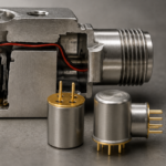
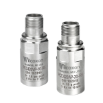
Wilcoxon currently offers Modbus as our native digital communication interface via the 883M triaxial accelerometer and temperature sensor. This was selected due to the wide deployment opportunities across PLC, DCS and SCADA systems while integrating directly into many plant-floor automation environments. For MQTT and OPC UA data delivery, Wilcoxon provides solutions such as the Vibration Data Source or Inline Adapter families, which convert traditional IEPE accelerometer signals into structured digital vibration data. These platforms enable time waveform, FFT and calculated vibration metrics to be delivered digitally, retaining proven IEPE accelerometers in the field for the types of environments that digital sensors aren't suited for, such as high-temperature, specialty applications, or hazardous areas.
The maximum number of registers per request on Modbus is 125. How do you transfer bigger time waveforms? For example a 130k samples waveform?
Modbus communication transfers large waveform datasets by storing them as contiguous data buffers that are retrieved through sequential register reads rather than a single request.
In Wilcoxon’s 883M digital accelerometer, Modbus registers are used to deliver both scalar vibration metrics and structured waveform and FFT datasets. The sensor provides 17 calculated health metrics per axis as individual scalar values for continuous monitoring. In addition, the sensor outputs waveform and FFT data within dedicated register ranges that represent structured data arrays rather than single scalar measurements.
When waveform or spectral data is requested, the client system reads these buffers in multiple register blocks. The monitoring or analytics software then reconstructs the full waveform or FFT dataset after retrieving the sequential register segments. This approach allows high-resolution diagnostic datasets to be transferred while remaining fully compliant with Modbus communication limits.
This segmented transfer method is commonly used for large vibration datasets because it supports reliable communication performance while preserving access to detailed diagnostic data. In most industrial deployments, waveform and spectral datasets are retrieved as snapshots or scheduled diagnostic captures, while overall vibration metrics are continuously polled for trending and alarming.
Some vibration faults need verification such as phase analysis confirmation. How is this phenomena tackled?
Certain vibration fault conditions, such as unbalance, misalignment, looseness, or resonance, often require verification using phase or order-based analysis. These techniques require a reference signal that is synchronized with shaft rotation, typically provided by a tachometer or speed reference input.
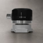
Wilcoxon’s VDS130 Vibration Data Source supports these applications by providing four simultaneous vibration input channels along with a dedicated tachometer input. The tachometer signal allows vibration measurements to be correlated with shaft position and rotational speed, enabling phase analysis, order tracking, and confirmation of fault sources.
By capturing vibration data alongside a synchronized speed reference, the VDS130 allows users to perform advanced diagnostic techniques that distinguish between similar fault signatures. This capability is especially useful for validating root cause conditions, performing balancing and alignment verification, and analyzing rotating machinery operating across variable speeds.
Won't using Modbus RTU cause a time delay between different transferred parameters from one sensor? For example, X and Y direction vibrations.
Both Modbus RTU and TCP/IP use client-server polling architecture, which means data values are read sequentially rather than simultaneously. However, in practical vibration monitoring applications, this typically does not introduce meaningful measurement delays between axes such as X, Y and Z, or different sensor locations. In the 883M digital accelerometer, vibration data from all three axes is captured simultaneously at the sensor level. The sensor samples and processes vibration data internally using synchronized acquisition before making calculated metrics or diagnostic datasets available through Modbus registers. Because the vibration measurements are acquired simultaneously inside the sensor, sequential Modbus polling does not affect the time alignment of the measurement data.
The Modbus communication simply retrieves already captured and processed data from memory. Any timing difference between register reads is typically on the order of milliseconds, which is typically negligible for trending and condition-based maintenance workflows.
For applications requiring precise time correlation between multiple channels or sensors, the VDS130 provides synchronized multi-channel data acquisition and timestamping, ensuring accurate phase and cross-channel diagnostic analysis when required.
Are there any limitations for samples in time waveform?
The time waveforms from our 883M Modbus triaxial accelerometer, VDS130 vibration data source, and family of Inline Adapters are all fixed intervals with rigid lines of resolution. Depending on the application, the VDS enables extending or shortening the time waveform to better capture equipment rotation, which the fixed sampling rate will be able to accurately capture. Likewise, the ILA family and 883M have fixed sampling rates to comprehensively capture vibration data across their full frequency ranges.
 EN
EN