Vibration data no longer lives exclusively inside dedicated condition monitoring software. It now feeds PLCs, SCADA systems, enterprise software, AI applications, and vibration SaaS platforms. As more organizations connect vibration data to operations, enterprise, and cloud systems, practitioners continue to face a familiar engineering question: should they choose a MEMS accelerometer or a piezoelectric accelerometer?
Modern digital vibration monitoring generally follows one of two approaches:
- Native digital accelerometers combine sensing, analog-to-digital conversion, and communications in a single device.
- Piezoelectric sensors + digital converters perform the vibration measurement at the sensor and digitize the signal externally using the protocol best suited to the application.
Although both approaches ultimately produce digital vibration data, they are not identical measurement systems. The sensing technology and location of the analog-to-digital conversion influence the quality and characteristics of the resulting data.
Digital output does not guarantee identical measurement quality. The quality of digital vibration data depends on the quality of the measurement before conversion.
Sensor Construction Influences Sensor Performance
The performance of any vibration measurement system begins with the sensor itself. Certain limitations originate with the sensor's physical construction, including:
- Frequency response
- Noise floor
- Dynamic range
- Temperature capability
- Environmental suitability
- Hazardous-area certification
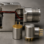
In MEMS-based accelerometers, vibration energy passes through internal mechanical structures before reaching the sensing element. Those structures can introduce internal resonances that limit usable frequency response. Compare that to an IEPE accelerometer, where the primary components are solid machined parts with higher, known resonances. The case of the sensor body itself is a hard, stainless-steel piece of metal, stiff so that it transfers vibrations well. Likewise, the base of the sensing element is designed to fit exactly where it needs to while maximizing sensor performance. The crystal is wrapped tightly around the center post, at least in shear-mode designs, with a known, high-frequency resonance, and the mass that acts on that crystal is also tightly controlled with metallic makeup. The simplicity and stiffness of these components enable high-frequency data to be effectively captured and brought into the electronics for processing.
MEMS sensors also introduce electronic and mechanical noise that help establish a practical noise floor. When measuring low-amplitude vibration signals, particularly at low frequencies where noise is of particular concern, that noise floor can limit the ability to detect and analyze subtle and slow-speed machine behavior. Piezoelectric sensors also have elevated noise at lower frequencies, inherent due to their design, but the key difference lies in the amplitude of the noise floor and how it changes with frequency.
In addition, MEMS-based devices contain integrated electronics that can introduce temperature-related limitations and complicate hazardous area certifications.
Frequency Response and Diagnostic Capability
Many MEMS-based digital accelerometers are designed for applications where vibration information is concentrated at lower frequencies and may have usable bandwidths of approximately 5 kHz or less. By comparison, piezoelectric sensors commonly provide usable frequency ranges extending well beyond 10 kHz and, in some cases, beyond 20 kHz.
Many machine faults generate vibration energy at higher frequencies before they become visible at lower frequencies. Higher-frequency measurements can improve detection of:
- Bearing defects
- Gear mesh problems
- Lubrication-related faults
- Other developing faults before they become apparent at lower frequencies
If those frequencies cannot be measured, the resulting digital data may still be valid, but important diagnostic information may not yet be available. In some applications, this can delay fault detection until the condition has progressed further and becomes visible at lower frequencies. The result is more impactful vibrations causing damage to the equipment and other machinery it may be coupled to, worsening the machine condition at a more rapid pace and raising maintenance and repair costs.
Noise and Low-Frequency Performance
Every measurement system has a noise floor. Below an acceptable signal-to-noise ratio, it becomes increasingly difficult to distinguish actual machine vibration from noise generated by the measurement system itself. Low-frequency measurements with relatively small vibration amplitudes are particularly sensitive to noise. The ability to distinguish meaningful vibration from background noise determines how useful data is for analysis and decision-making.
MEMS-based sensors have essentially constant noise across their entire usable bandwidth and typically exhibit higher noise floors than piezoelectric sensors, making low-amplitude signals more difficult to detect or analyze. This can be important when monitoring:
- Slow-speed assets, like large fans and kilns
- Large rotating equipment, including motors
- Structural vibrations
- Other applications where low-frequency information carries significant diagnostic value
Piezoelectric sensors generally maintain lower noise floors, extending the range of usable measurements and improving visibility into subtle machine behavior. Unlike MEMS sensors that exhibit consistent noise, piezoelectric noise increases at lower frequencies, a condition called thermal, or Johnson, noise. This is a known condition but the amplitude of that low-frequency, elevated noise floor is still typically lower than that of a MEMS sensor.
IEPE accelerometers benefit from decades of application-specific sensor development and are generally available in a broader range of sensitivities and specialty designs. For example, when measuring very low-frequency, low-amplitude vibration, like large fans, practitioners frequently select higher-sensitivity IEPE sensors, such as 500 mV/g or greater designs, with further reduced noise and improved resolution at low speeds and very low frequencies.
Environmental Fit
Environmental conditions are often just as important as measurement performance when selecting a sensing architecture. Long-term reliability must be considered within the context of the operating environment.
Many digital MEMS accelerometers are designed for industrial environments and provide excellent performance in a wide range of applications. However, the integrated electronics required for sensing, signal conditioning, analog-to-digital conversion, and communications can introduce environmental limitations that must be considered during system design.
Temperature is one such example. Electronic components within MEMS sensors typically have operating temperature limits that may be lower than those achievable with piezoelectric sensing technologies.
- When operating temperatures exceed +70° C, available MEMS options become more limited.
- The minimum operating temperature of MEMS sensors is typically –20° C.
- Piezoelectric sensors are widely available with operating temperatures to +165°C, and specialty sensors can withstand even hotter environments.
- Piezoelectric sensors are regularly rated as low as –50° C, with some available for cryogenic applications.
Housing construction is another consideration. Materials, sealing methods, ingress protection (IP rating), and resistance to chemicals or washdown environments may influence the selection of a MEMS or piezoelectric sensor. An aluminum housing, typical of MEMS digital sensors, is great for indoor environments such as factory or process automation - but exposing it to cooling tower drift or a corrosive paper plant can have adverse effects.
Piezoelectric sensors have a long history of use in harsh industrial applications:
- High-temperature and cryogenic environments
- Washdown, spray-down, and submerged locations
- Corrosive processes
- Outdoor installations
- Nuclear and radioactive environments
Hazardous Areas
Applications involving flammable gases, vapors, dusts, or other hazardous conditions often require compliance with standards such as Intrinsic Safety, also known as Class 1 Division 1 or ATEX Zone 0/1, and Class 1 Division 2 or Zone 2. These certifications prevent installed sensors from becoming an ignition source within the hazardous environment.
Because digital accelerometers integrate sensing, signal conditioning, analog-to-digital conversion, and communications electronics within the sensor itself, achieving and maintaining certification can be more complex, and there are few such sensors available today.
There are a wide variety of hazardous-area-certified IEPE sensors. Installing the converter in a non- or less-hazardous location allows conversion and communications electronics to live outside the high-risk area. The result is a practical path to digital vibration data that maintains compliance with hazardous-area requirements while still supporting modern digital workflows, including control systems, enterprise platforms, cloud architectures, and vibration analysis applications.
Choosing the Right Technology
MEMS and piezoelectric accelerometers are both viable options for digital vibration monitoring. Neither technology is universally better—the right choice depends on the measurement objectives, operating environment, and diagnostic requirements of the application.
MEMS-based digital accelerometers provide an effective and economical solution in:
- General-purpose monitoring applications
- Balance-of-plant applications
- Mild industrial environments
Piezoelectric accelerometers are generally preferred when applications require:
- Wider frequency response
- Lower noise floors
- Higher operating temperatures
- Hazardous-area certifications
- Specialty sensor configurations
- Critical equipment monitoring
Paired with a digital converter, they can deliver the vibration data using known digital protocols while preserving the measurement performance required of some more demanding industrial applications.
The following table summarizes the general characteristics of each approach and provides a practical starting point for selecting the sensing technology that best fits your application.
| Consideration | MEMS Accelerometer | Piezoelectric Sensor + Converter |
| High-frequency response | General purpose monitoring, ~5 kHz | High-frequency diagnostics, 10-20+ kHz (gear mesh, high speed, lubrication faults) |
| Low-frequency performance | General purpose monitoring, ~2 Hz | Low-frequency applications, ~0.05 Hz (slow-speed assets, fans) |
| Noise floor | Suitable for many industrial applications | Optimized for lowest-noise applications |
| Environment | Mild factory environments, indoor applications | Harsh environments, hazardous areas, high temperatures, and specialty applications |
 EN
EN ENGLISH